Tuesday, August 28, 2012
Fundamentals of Mass Balances (Part 2)
Balances
The General Balance Equation
Supposes methane is a component of both input and output streams of a continuous process unit, and that in an effort to determine whether the unit is performing as designed, the mass flow rates of methane in both streams are measured and found to be different (min
≠ mout).

There are several possible explanations for the observed difference between the measured flow rates :
- Methane is being consumed as a reactant or generated as a product within the unit
- Methane is accumulating in the unit, possibly adsorbing on the walls
- Methane is leaking from the unit
- The measurements are wrong
A balance on a conserved quantity (total mass, mass of a particular species, energy, momentum) in a system (a single process unit, a collection of units, or an entire process) may be written in the following general way :
There are 2 types of balances :

- Differential balances. A balance that indicates what is happening in a system at an instant in time. Each term of the balance equation is "rate" (rate of input, rate of generation, etc) and has units of the balanced quantity unit divided by a time unit (people/year, gr/s, barrels/day, etc). This is the type of balance usually applied to a "continuous process."
- Integral balances. A balance that describe what happens between two instants of time. Each term of the equation is an "amount" of the balanced quantity and has the corresponding unit (people, gr, barrels). This type of balance is usually applied to a "batch process", with the two instants of time being the moment after the input takes place and the moment before the product is withdrawn.
- If the balanced quantity is total mass, set generation = 0 and consumtion = 0. Except in nuclear reactions, mass can neither be created nor destroyed
- If the balanced substance is a nonreactive species (neither a reactant nor a product), set generation = 0 and consumption = 0
- If a system is at steady state, set accumulation = 0, regardless of what is being balanced. By definiton, in a steady-state system nothing can change with time, including the amount of the balanced quantity
Thursday, August 23, 2012
Fundamentals of Mass Balances (Part 1)
Fundamentals of Mass Balances
 |
| Basic Diagram of Mass Balance |
Introduction
Certain restriction imposed by nature must be taken into account when designing a new product or analyzing the existing one. You cannot, for example specify an input to a reactor of 1000 g of lead and an output of 2000 g of lead or gold or anything else.
Similarly, if you know that 1500 lbm of sulfur is contained in the coal burned each day in a power plant boiler, you do not have to analyze the ash and stack gases to know that on the average 1500 lbm of sulfur per day leaves the furnace in one form or another.
The basis for both of these observation is the "the law of conservation of mass", which states that mass can neither be created nor destroyed.
The statement based on "the law of conservation of mass" such as :
Total mass of input = Total mass of output
is called by mass balances or material balances.
The design of a new process or analysis of an existing one is not complete until it is established that the inputs and outputs of the entire process and of each individual unit satisfy balance equations.
Process Clasification
Chemical processes may be classified :
- Batch Process. The feed is charged (fed) into a vessel at the beginning of the process and the vessel contents are removed sometime later. No mass crosses the system boundaries between the time the feed is charged and the time the product is removed. Example : Rapidly add reactants to a tank and remove the products and unconsumed reactants sometime later when the system has come to equilibrium.
- Continuous Process. The inputs and outputs flow continuously throughout the duration of the process. Example, pump a mixture of liquids into a distillation column at a constant rate and steadily withdraw product streams from the top and bottom of the column.
- Semi-Batch Process. Any process that is neither batch nor continous. Example, allow the contents of a pressurized gas container to escape to the atmosphere; Slowly blend several liquids in a tank from which nothing is being withdrawn.
If the values of all the variables in a process (temperatures, pressures, volumes, flow rates) do not change with time, except possibly for minor fluctuations about constant mean values, the process is said to be operating at steady state. If any of the process variables change with time, transient or unsteady-state operation is said to exist. By their nature, batch and semi-batch processes are unsteady-state operations, whereas continuous processes may be either steady - state or transient.
Batch processing is commonly used when relatively small quantities of a product are to be produced on any single ocassion, while continuous processing is better suited to large production rates. Continuous processes are usually run as close to steady state as possible; unsteady-state (transient) conditions exist during the start-up of a process and following changes in process operation conditions.
Tuesday, August 21, 2012
Flow Sheet
Flow Sheet
 |
| Flowsheet Example |
Definition
Flowsheet is a diagram showing the progress of material through a preparation of treatment plant. It shows the material and energy flow in each unit process and unit operation in plant process.1. Basic Valve Symbols

2. Basic Instrumentation Symbols

3. Basic Pump & Tank Symbols

4. Basic Compressor, Turbin, & Motor Symbols

5. Basic Heat Exchanger & Cooling Tower Symbols

6. Basic Furnace & Boiler Symbols

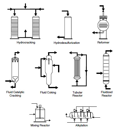
7. Basic Reactor Symbols
Subscribe to:
Posts (Atom)
Visitors
